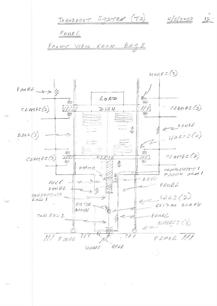
The trolley in the transport system contains a dish for holding the load. A compression plate is mounted underneath the dish and there are four springs fitted between the dish and the plate. Four guide rods run through the dish and plate and to the panel at the bottom of the trolley. They are there to stabilize the dish and plate during operation. Here is another view (front view) of the trolley as seen from Bay 2. This image shows the SCM, the compression plate along with the springs and the load; clamps at the dish and plate are also shown. These are manually operated clamps used to operate the transport system. Their operation will be explained later along with their design.
A rack is vertically attached underneath the compression plate that carries the load; it is pushed up and down by the compression plate. The rack drives a pinion mounted on a crankshaft. The pinion meshes with the moving rack and rotates. The pinion drives the crankshaft to rotate it as well.
The size of the pinion compared to the rack (number of teeth) determines the gear ratio. The ratio affects the amount of force required to move the rack and the resulting movement of the slider block and wheel.
Note: If a compression plate gear reduction system is employed, a small vertical movement of the rack translates to a large number of rotations of the wheel.
An image with description of a crankshaft plus crank arm can be seen here >>
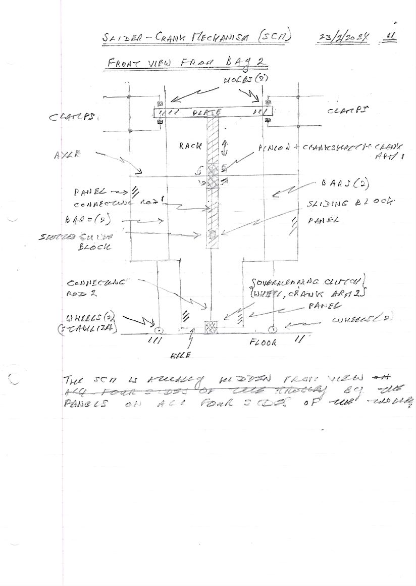
A connecting rod attached to the crank arm on the crankshaft drives a slider block below it. Here is a side view of the slider-crank mechanism (SCM) with Bay 1 on the left and Bay 2 on the right. Here is another view of the SCM as seen from Bay 2. We shall call this view a front view. This image shows how the SCM is integrated in the trolley. The SCM moves up and down with the compression plate in the trolley. The SCM is attached to the trolley panel walls, the plate and the wheel on the ground. The trolley is enclosed on all four sides and at the bottom by panels.
Slider Block: This is a block connected to the crank arm by means of a connecting rod. The slider block moves up and down and is constrained by a guide on the panel. The guide has a slot in it, which holds the slider block and allows it to move up and down.
Slider Block Movement: One end of the connecting rod is attached to the slider block. As the crank arm pivots, the connecting rod swings back and forth, causing the slider block to move vertically within its slot in the guide block. This is a well established method. The movement of the slider block (which is vertical) is constrained by a slotted guide block. The slider block is connected to a second connecting rod which is attached to a lever arm on a second crankshaft at the wheel on the ground. An overrunning clutch on the wheel ensures uni-directional motion of the wheel and thus the trolley.
Connecting Rod 2: This connects the slider block to crankshaft #2 at the wheel. The vertical motion of this connecting rod causes the crankshaft to rotate. The crankshaft is attached concentrically to the wheel. The motion of the slider block-con rod 2 assembly is reciprocating motion. But an overrunning clutch on the crank eliminates the reverse motion of crankshaft 2 and the wheel and causes uni-directional motion.
Connecting Rod 2 Pivoting: The connecting rod pivots due to the slider block's vertical movement. Since it is angled relative to the vertical movement and connected to the wheel axle (or a mechanism near the wheel), the pivoting motion translates into a horizontal movement of the wheel's contact point with the ground.
Connecting Rod 2 Angle: The angle of connecting rod 2 relative to the vertical movement is crucial for achieving the desired horizontal movement of the wheel. A steeper angle will result in a larger horizontal movement for the same vertical displacement of the slider block.
Wheel/Crank: The crank rotates in response to the motion of the con rod thus driving the wheel. An overrunning clutch mechanism on the crankshaft ensures uni-directional motion of the wheel. Gearing may be introduced between the crank and the wheel to affect the speed and torque of the wheel rotation. This would allow for adjustment in the mechanism's performance and it would introduce a gear ratio.
Go to Introduction