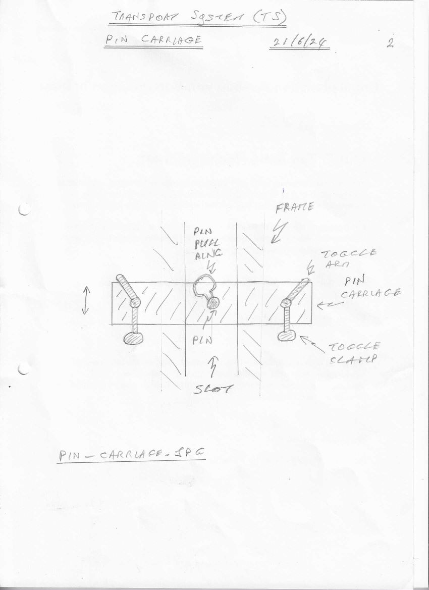
Pins are used in the system to secure and position the dish and plate. The pins are an important interface between the operator and the trolley mechanism.
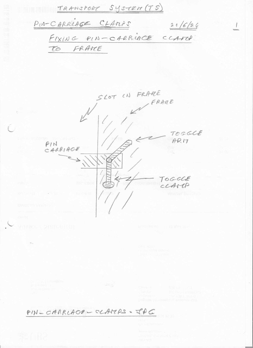
There are two dish pins. Each pin is mounted on a carriage, which can be moved up and down in a slot in the frame. There are two slots one at the front and one at the rear of the trolley. All pins in the system are the same. The pin is a spring-loaded device operated by pulling a ring attached to it. The pin carriage has two toggle clamps attached to it, one at each side. The clamps are used to fix the pin carriage to the frame at the required elevation.
The pin carriage is moved by raising and lowering it in the slot in the frame until it is at the desired height. The pin should be aligned with the hole in the dish; the pin is then released by operating the ring on the pin and the pin enters the hole in the dish. The two toggle clamps on the pin carriage are now operated to fix the carriage tightly against the frame. The same is done with the pin on the other side of the dish. The pins hold the dish in place when the trolley arrives at Bay 2 and during the unloading process there. They are disengaged when the trolley travels from Bay 1 to Bay 2, and back, to allow the load and the springs to release energy and drive the TS system.
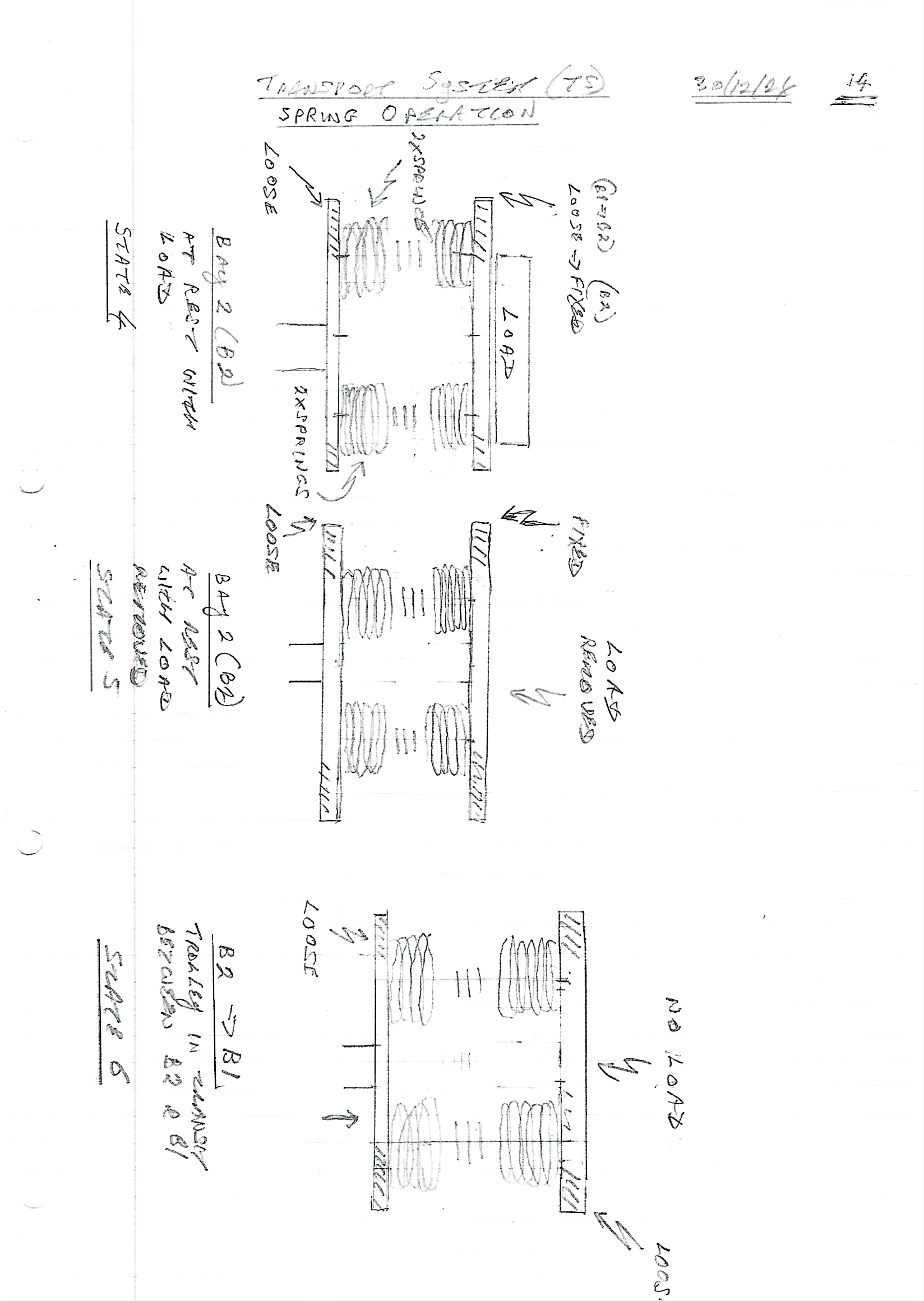
State 4: Depending on the size of the load, the dish will stop at a specific position relative to the frame. The operator positions the two pin carriages to suit the elevation of the dish. They then engage the pins with the holes in the dish to fix the dish in position. The plate is left loose.
There are two plate pins. Each pin is mounted on a carriage, which can be moved up and down in a slot in the frame. There are two slots one at the front and one at the rear of the trolley. All pins in the system are the same. The pin is a spring-loaded device operated by pulling a ring attached to it. The pin carriage has two toggle clamps attached to it, one at each side. The clamps are used to fix the pin carriage to the frame at the required elevation.
The pin carriage is moved by raising and lowering it in the slot in the frame until it is at the desired height. The pin should be aligned with the hole in the plate; the pin is then released by operating the ring on the pin and the pin enters the hole in the plate. The two toggle clamps on the pin carriage are now operated to fix the carriage tightly against the frame. The same is done with the pin on the other side of the plate. The pins hold the plate in place when the trolley is stationary at Bay 1 and while it is being loaded there. They are disengaged when the trolley travels from Bay 1 to Bay 2, and back, to allow the load and the springs to release energy and drive the TS system. They are disengaged when the trolley is stationary at Bay 2 and while it is being unloaded there.
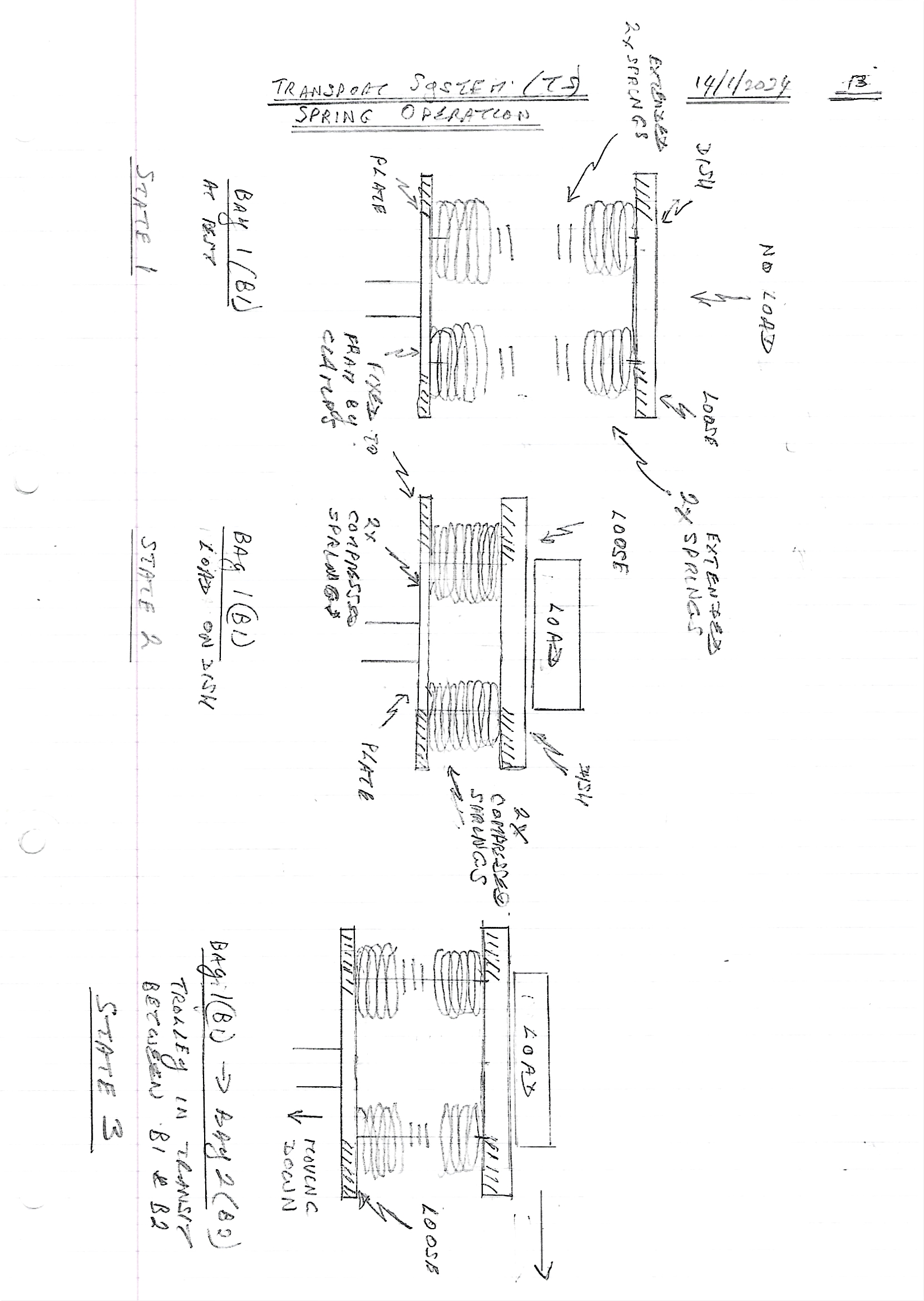
State 1: The plate pins are always inserted in the plate at the same position on the frame. The plate pins are positioned on the frame by the operator at the maximum upper position. This is an adjustable position at the transition between fully relaxed springs and the springs starting to come under tension (because the dish pins are stopped from rising at some point by a mechanical stop on the frame). The plate is fixed by the operator with the pins where the plate is at rest or comes to rest having travelled from Bay 2 to Bay1. The pins can be moved up and down by the operator through vertical slots in the frame.
At some stage the design will need to be augmented with a chock at the wheel on the ground to keep it stationary while the pins are being engaged and disengaged by the operator at Bays 1 and 2. The check is removed by the operator to allow the trolley to travel when required.
Go to System Operation
Go to Introduction