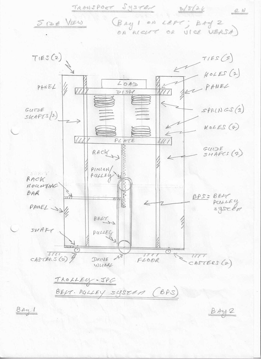
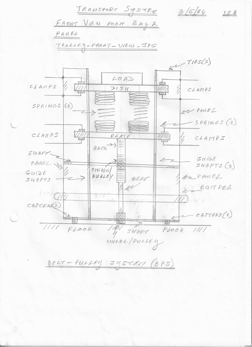
The trolley in the transport system contains a dish for holding the load. A compression plate is mounted underneath the dish and there are four springs fitted between the dish and the plate. Four guide shafts run through the dish and plate and to the frame at the bottom of the trolley. They are there to stabilize the dish and plate during operation. Here is a front view of the trolley as seen from Bay 2. This image shows the BPS (belt-pulley system), the compression plate along with the springs and the load; clamps at the dish and plate are also shown. These are manually operated clamps used to operate the transport system.
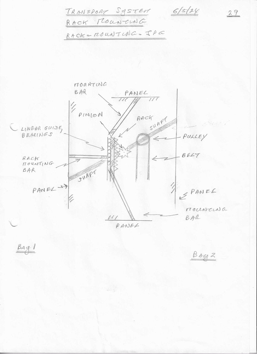
A rack is vertically attached underneath the compression plate that carries the load; it is pushed up and down by the compression plate. The rack is supported by a linear guide and bearings, which are attached to the side panels by mounting bars. The rack drives a pinion mounted on a crankshaft, which is attached to two side panels. The pinion meshes with the moving rack and rotates. The pinion drives the crankshaft to rotate it as well.
The size of the pinion compared to the rack (number of teeth) determines the gear ratio. The ratio affects the amount of force required to move the rack and the resulting movement of the belt, pulleys and the wheel.
Note: If a compression plate gear reduction system is employed, a small vertical movement of the rack translates to a large number of rotations of the wheel.
A pulley mounted on the pinion shaft drives a belt, which in turn drives another pulley mounted on the wheel shaft at the bottom of the trolley.
Go to Introduction