Some type of spring-loaded buffer could be used to stop the trolley when it arrives at Bay 1 or Bay2. These buffers are used on railways to stop trains. A bumper would be needed on the trolley as well to take the impact from the buffer on the track. I envisage that the trolley will be travelling quite slowly so the impact shouldn't be too great.
A dock bumper could be used as well. Here is an image of a dock bumper used at docking bays for trucks [27].
Another option is to use a mechanical stop on the track itself to stop the wheel. Here is an image of a mechanical stop used on tracks [28]. The trolley could tilt on impact though.
A block could be also be used on the track [28].
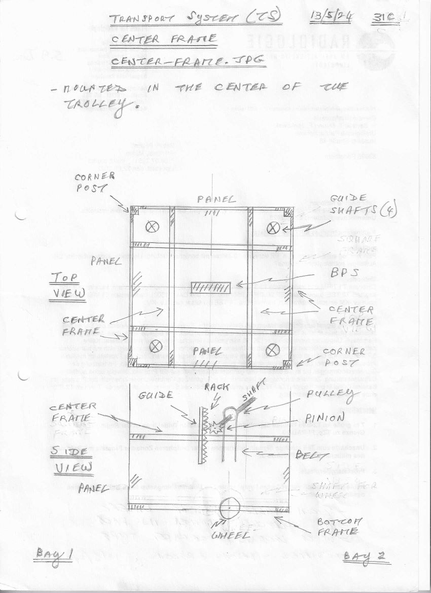
Frame at the very top and around the sides as a square fit.
Frame element below travel of rack or in the middle of the trolley leaving room for the rack to travel through.
The trolley probably needs to be quite tall with a long rack and a long belt to be able to travel some distance. The load probably needs to be sizeable as well to transmit enough of its potential energy to the trolley. The springs will also have to be quite big and strong to hold and transmit enough energy to the BPS. Some sort of gearing may be needed for a smooth gradual transmission of the power from the springs (compression plate) to the rack-pinion-BPS.
The problem now is what are the actual numbers here. What are the relationships between the load, springs, rack travel, belt length, and distance travelled? And do these proportions scale linearly?
Need to design the gearing at the rack and pinion to evenly transfer power from rack to pinion and then to the drive pulley for the belt. Gears need to withstand the force of the pinion and transfer power slowly to the pulley.
The shaft turns a larger gear that turns another shaft that then turns the pulley. Slow turning of the pinion shaft causes a faster turning of the pulley shaft, so a slow downward push of the plate causes a faster turning of the wheel on the ground.
Need to design and build a much taller prototype that would travel a good distance right from the start or to go with the more workable size chosen in the design so far. I think it is better to work with a smaller design at the beginning. It is more manageable and the system should be fairly easy to scale at a later date when most of the quirks and issues have been cleared.
Go to Introduction